...working in tandem with Raspberry Pi
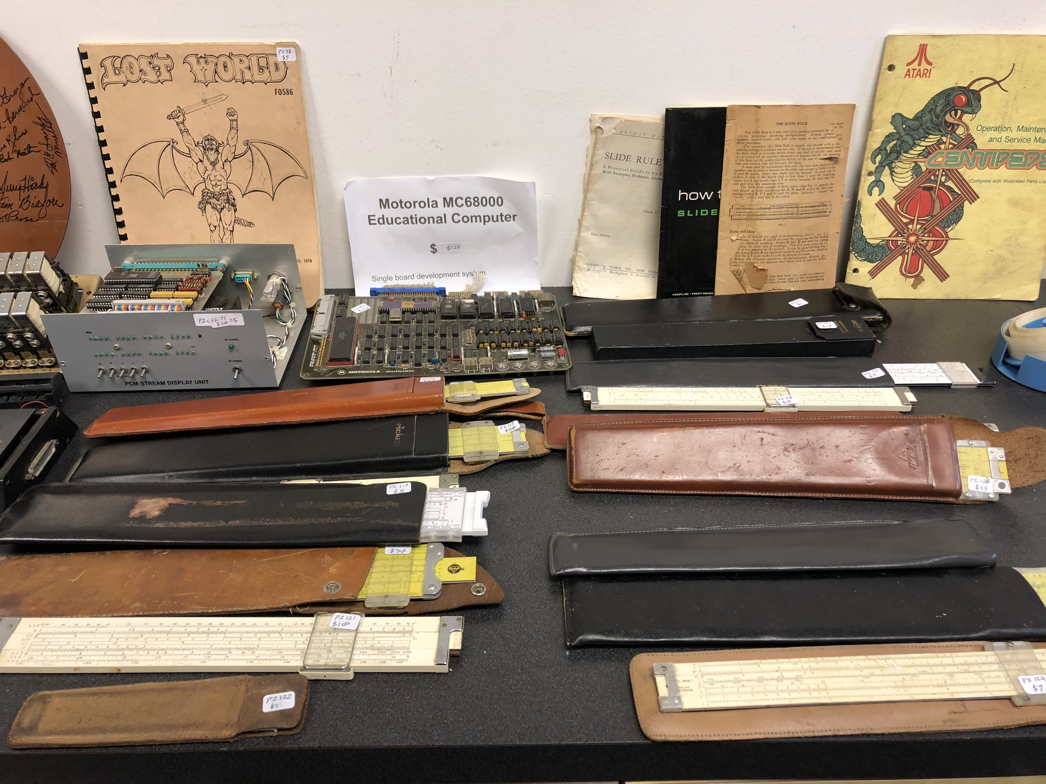
Motorola introduced the 68K processor in 1979, and it took the home computing world — and not only home computing world — by the storm. In the microcomputer world of the late 70s and early 80s dominated by 8-bit processors and machines like Commodore 64 and ZX Spectrum 48K, the 16-bit (or 32-bit depending on how one looks at it) Motorola 68000 seemed to provide endless possibilities. No wonder the original 68K and its later variants were soon to be used in new machines which would have changed the world of personal computing forever, including Apple Lisa and Macintosh, NeXT, several generations of Amiga and Atari ST, game consoles including Sega Genesis, HP printers, and even advanced calculators. The M68K didn't need excessive promotional efforts as its capabilities would speak for themselves, but that didn't stop Motorola from offering ways to encourage self-education and development for the new platform. One of such efforts was Motorola 68000 Educational Computer Board (MEX68KECB) introduced in 1981 and aimed at students and engineers needing hands-on experience with the new processor. ECB was not the first development/educational board by Motorola (for example their D2 board, made for the earlier-generation 6800 CPU, had been quite popular on the market), but it seems to have been the first to gain significant adoption in colleges.
Motorola 68000 Educational Computer Board (ECB) is a complete computer with a CPU, RAM and ROM memory, programmable timer, and I/O capabilities. All the user needs to do to start working is connect power and a serial terminal, even though a more common way of using the ECB board — in particular in US colleges — seemed to be connecting it to a time-shared host computer rather than a dumb terminal. A programmer would edit the code on the host computer, and then transfer it to the ECB for debugging purposes. Programs (in the form of memory content) could also be uploaded from the ECB to the host computer. There is a separate serial connection on the ECB for such communication with the host.
A very thoughful move on Motorola's part was to include a tutorial software in the ECB's ROM memory. The software — named TUTOR — provided debugging and basic assembly/disassembly functions as well as routines to dump or load memory content to the host computer or other I/O devices.
The board is also accompanied by an excellent manual, convering everything from basic connections and setup, to basic and advanced TUTOR description, to board schematics, detailed list of parts, and detailed description of every signal line protocol across the boards all interfaces. It is a fascinating read on its own, but for those aming to understand and practice the development for Motorola 68000 CPU good additional reading would be a book on practical aspects of programming for Motorola 68K, e.g. 68000 Assembly Language Programming by Lance A. Leventhal. There were even books published with exercises specifically crafted for the ECB board, e.g. Microcomputer Experimentation with the Motorola MC68000ECB by the same author Lance A. Leventhal.
This article is the log and documentation for a small project: making a Raspberry Pi work with the Motorola 68000 Educational Board as both dumb terminal and host machine and thus provide a real, non-emulated training and development environment for learning the 68K architecture. If you prefer watching to reading, I made a video which covers the building of this project:
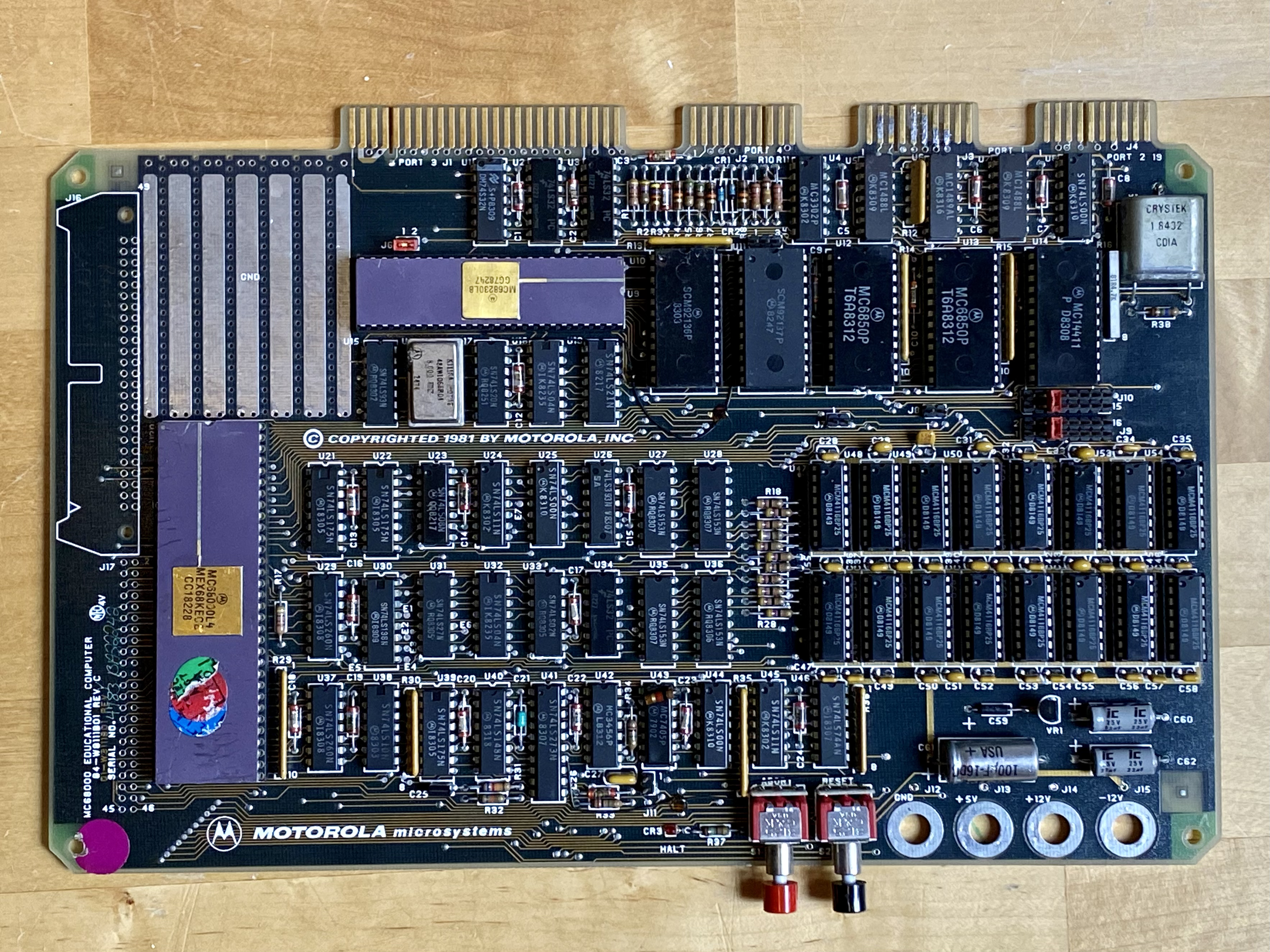
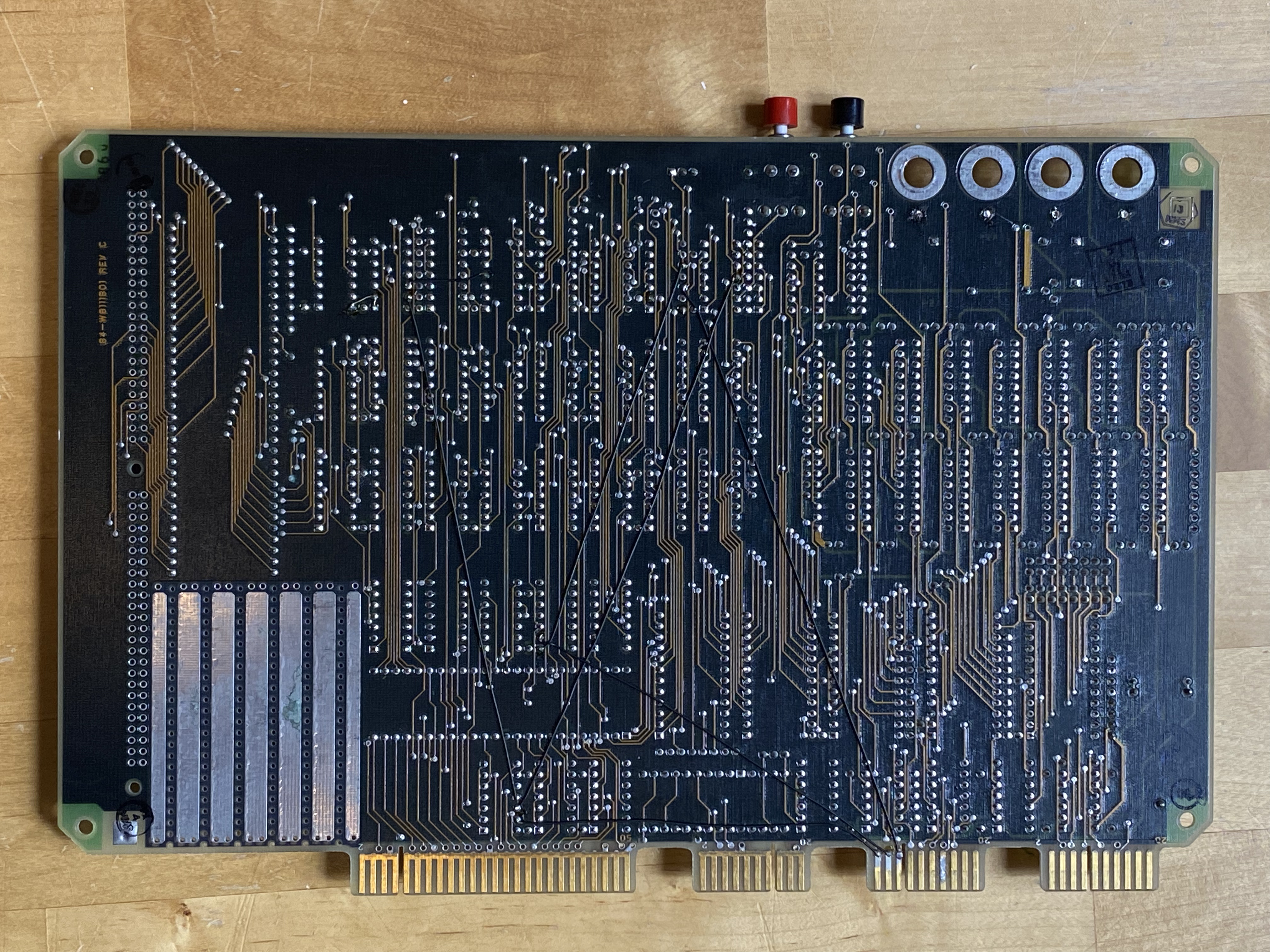
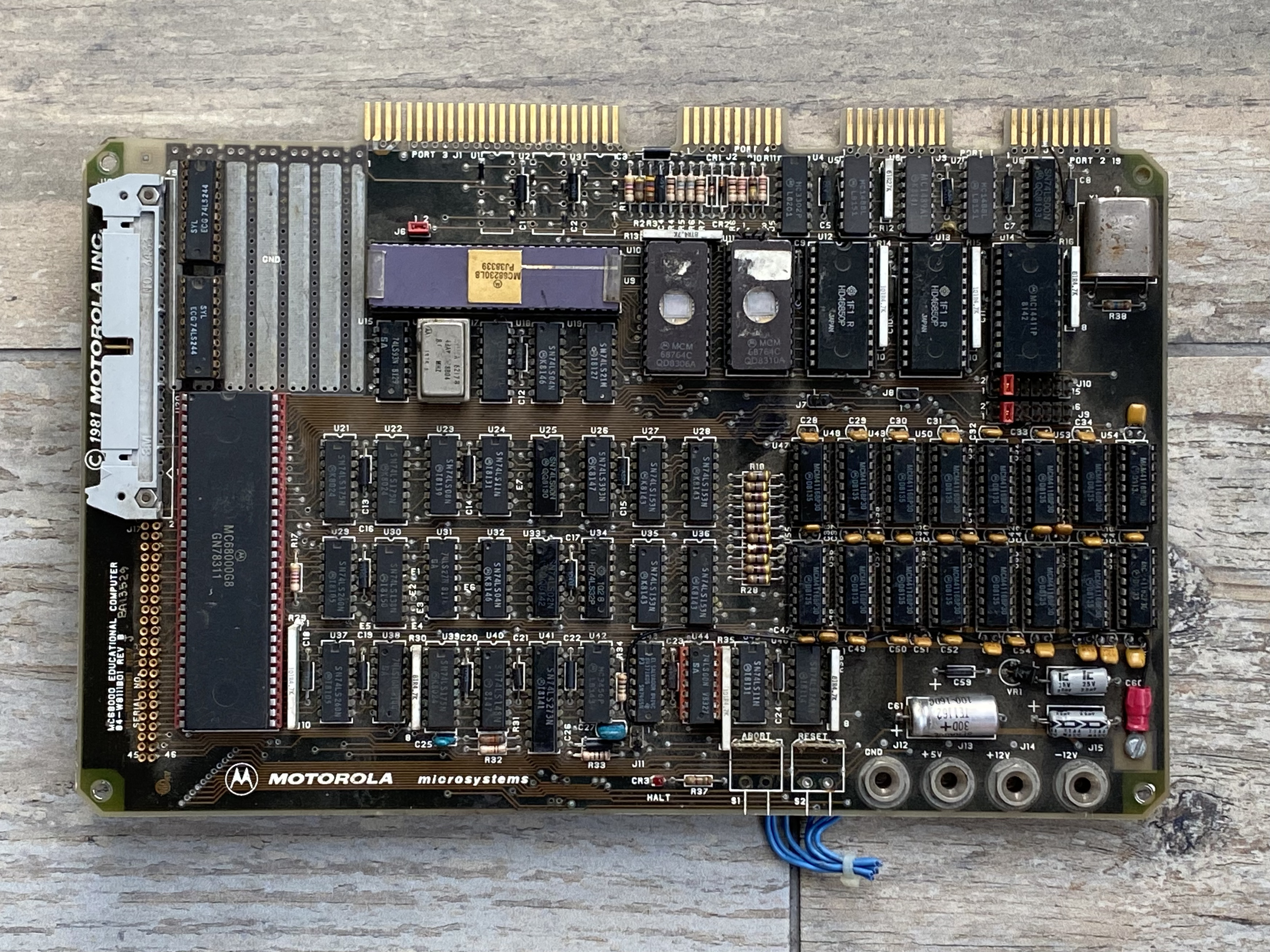
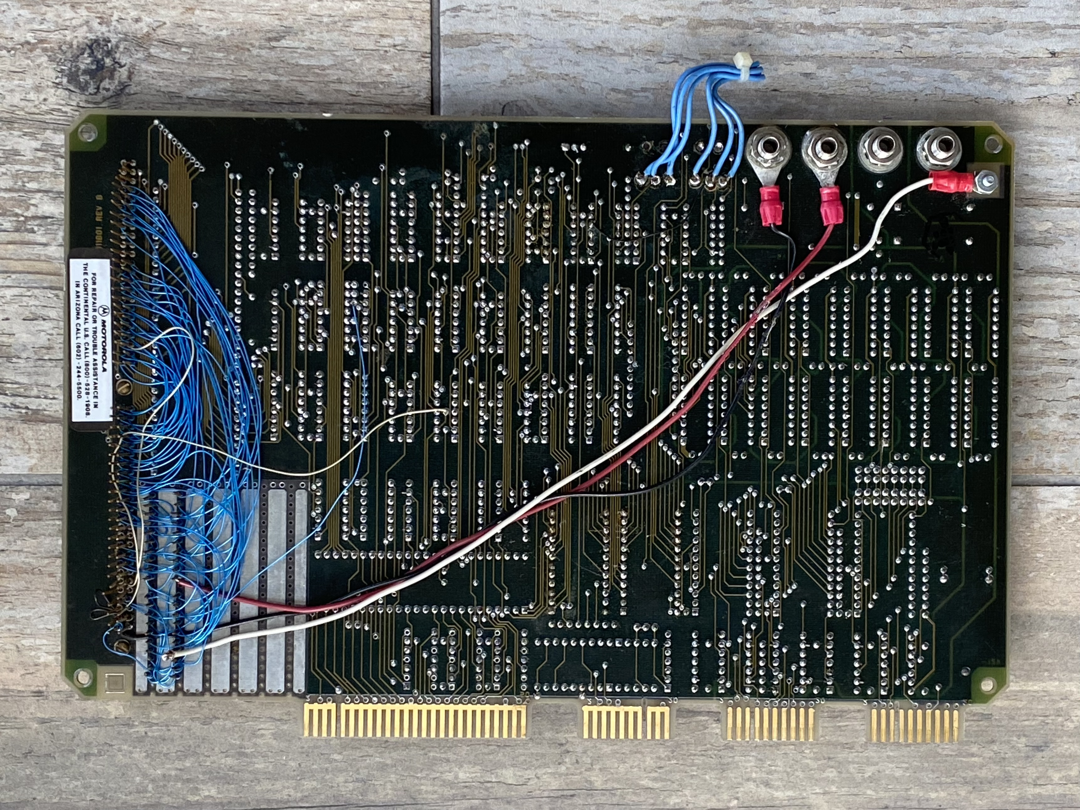
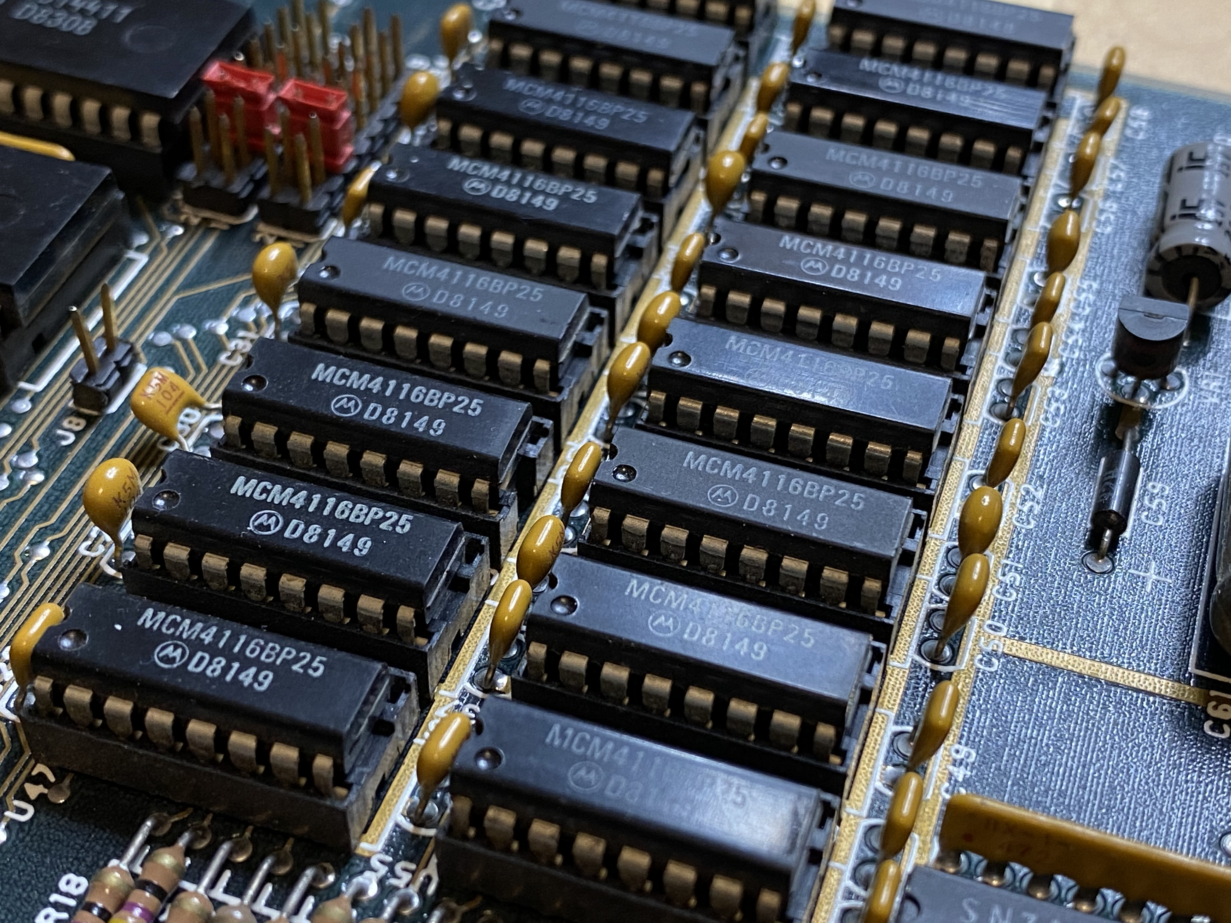
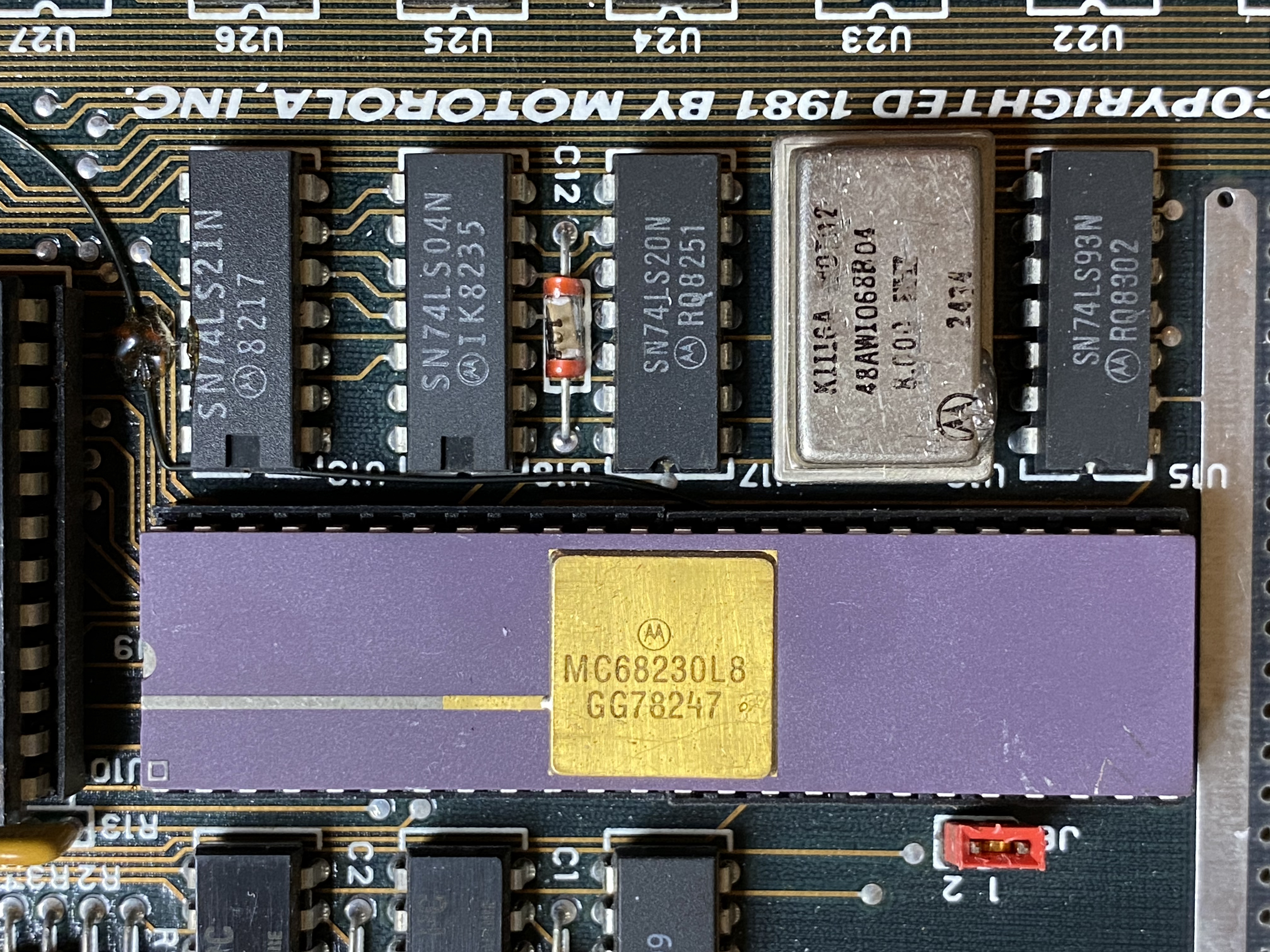
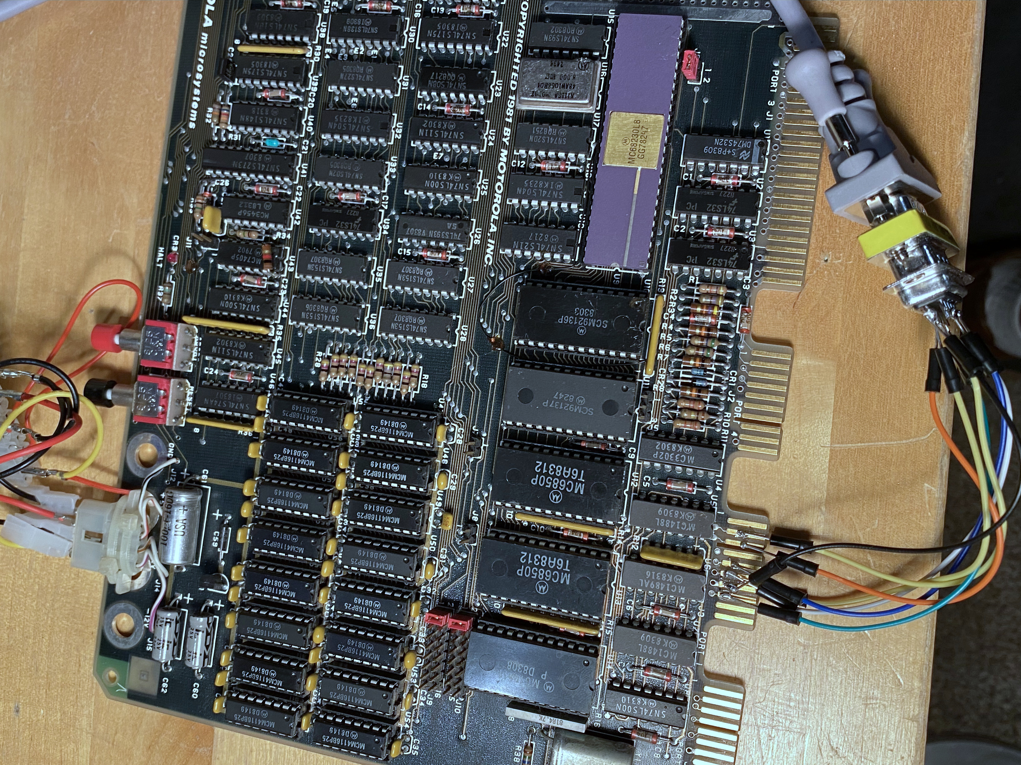
Except for a keyboard, display and power supply, Motorola 68000 Educational Computer Board is a complete computer on a single 267x165mm PCB (not including edge connectors). The 68000 CPU is clocked at 4MHz by an 8MHz crystal oscillator whose clock rate divided by 2 using a counter chip. 32K of RAM is an amount comparable to home computers of that era, and enough for serious experimentation. Memory is controlled by separate memory control logic and address multiplexer chips (Motorola would include memory management logic within the CPU only starting from 68030 generation of the processor). There are two RS232 ports, one for connecting a dumb terminal, another for data exchange with a host computer. There are also a parallel interface (e.g. for printer), and an audio interface for tape data storage. Users can also take advantage of the built-in 24-bit programmable timer, and a wire-wrap area where I/O connections are exposed for experimentation with additional circuitry.

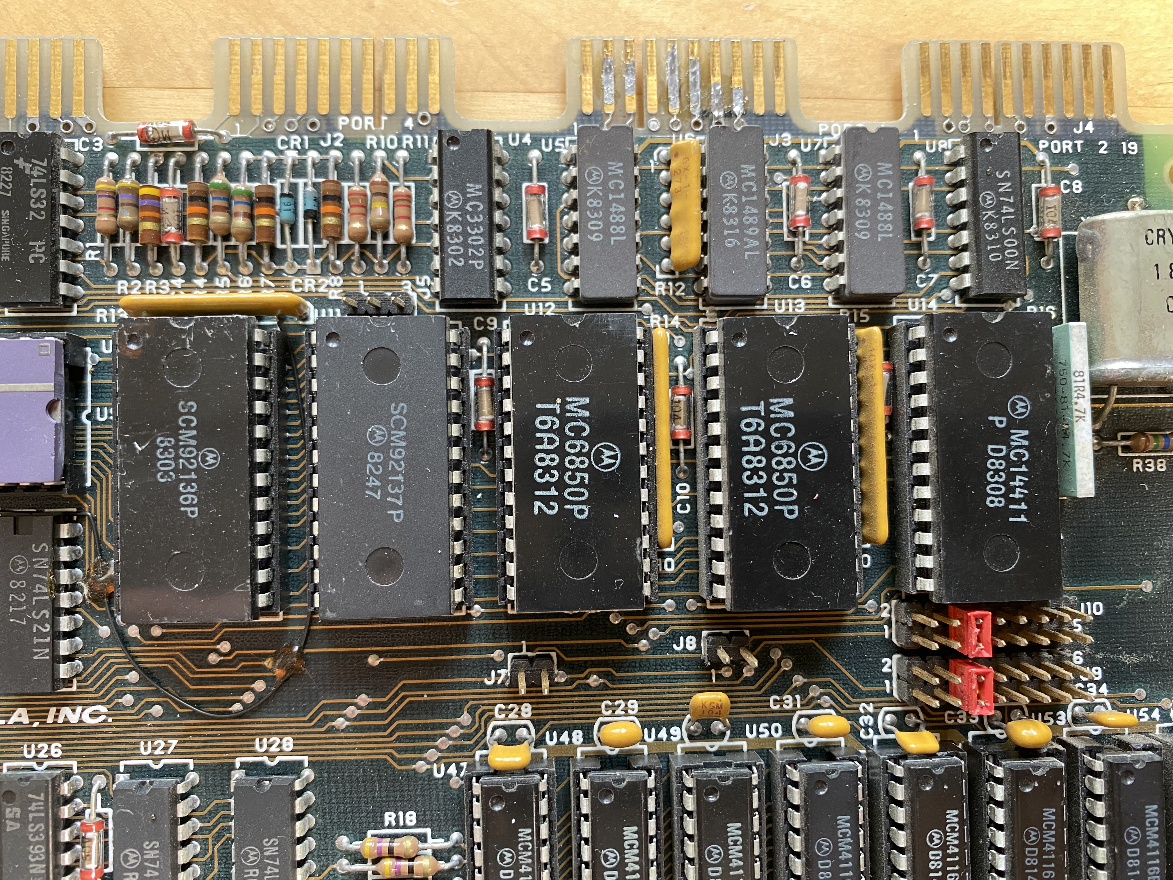
Two large ROM chips on the board contain 16K of debugging, monitoring, stepping and assembly/disassembly environment called TUTOR. The environment is operated using a command line interface via a serial link, and there is no GUI. As a matter of fact, the board does not provide any graphical capabilities, as there is no GPU or logic to address an arbitrary screen pixel or area — the implementation is purely textual. Which is one of the reasons Motorola was able to offer a really low price on the ECB. Despite containing then-state-of-the-art CPU, it cost only $495. For perspective, the Commodore 64 introduced a year later and based on much less capable 8-bit architecture but with additional sound and graphics chips cost a hundred dollars more.
Selected aspects of the TUTOR software and its built-in helper routines will be discussed further into the article; for comprehensive coverage see the printed ECB manual.
I have two of these boards. The one I bought 2018 Vintage Computer Fair in Mountain View Computer History Museum is really beat-up, so for my project — to avoid frustration — I decided to use the much cleaner-looking one I purchased on eBay later. Only once I succeed in getting the connections right and building the project will I attempt to re-vive the one in poorer condition.
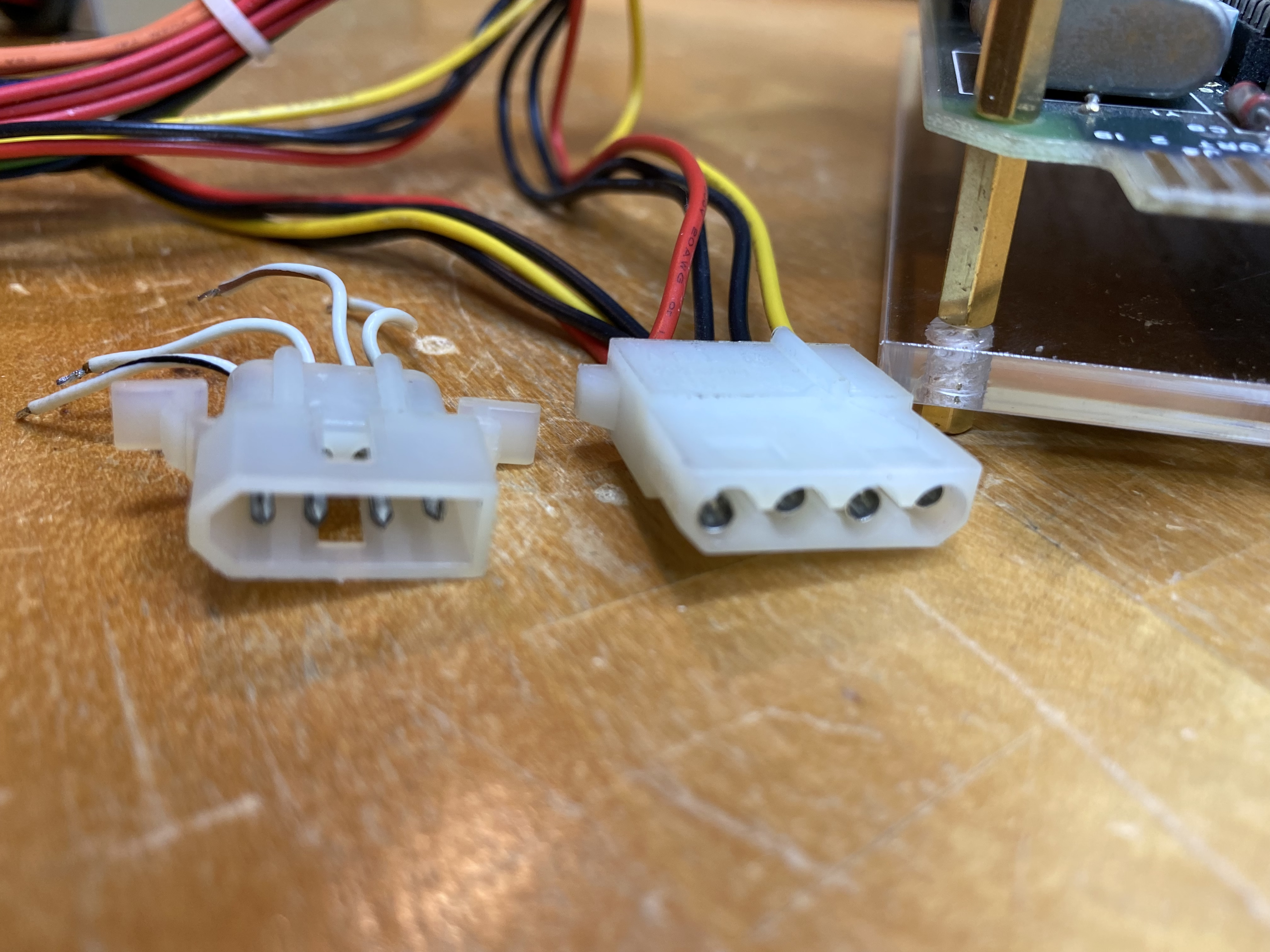
Before embarking on my project (which I vaguely defined in my head as "somehow connect Motorola ECB to Raspberry Pi"), I wanted to check if the board was actually operational. The manual goes to great lengths to warn against incorrect voltage application, so I was extra careful in how I connected a modern ATX power supply. Apparently applying +5V before +12V could cause damage to memory chips. A correct ATX power supply should be able to supply both voltages at the same time, or even +5V with a slight delay, which was what we wanted. I measured the levels in the power supply which I've taken out of an old PC, and carefully connected the live and ground wires. The ECB board I used had some kind of power socket attached for convenience which looked like smaller Molex connector; I wanted to buy a matching plug, but I realized I have no idea what type of Molex that was, or even if it was a Molex in the first place (after publishing this article I was advised that this was a "Molex 0003062042, part of their Standard .062 line"). I ended up connecting the wires one by one, with the plan to remove the old plug altogether when I get to assembling the final build.
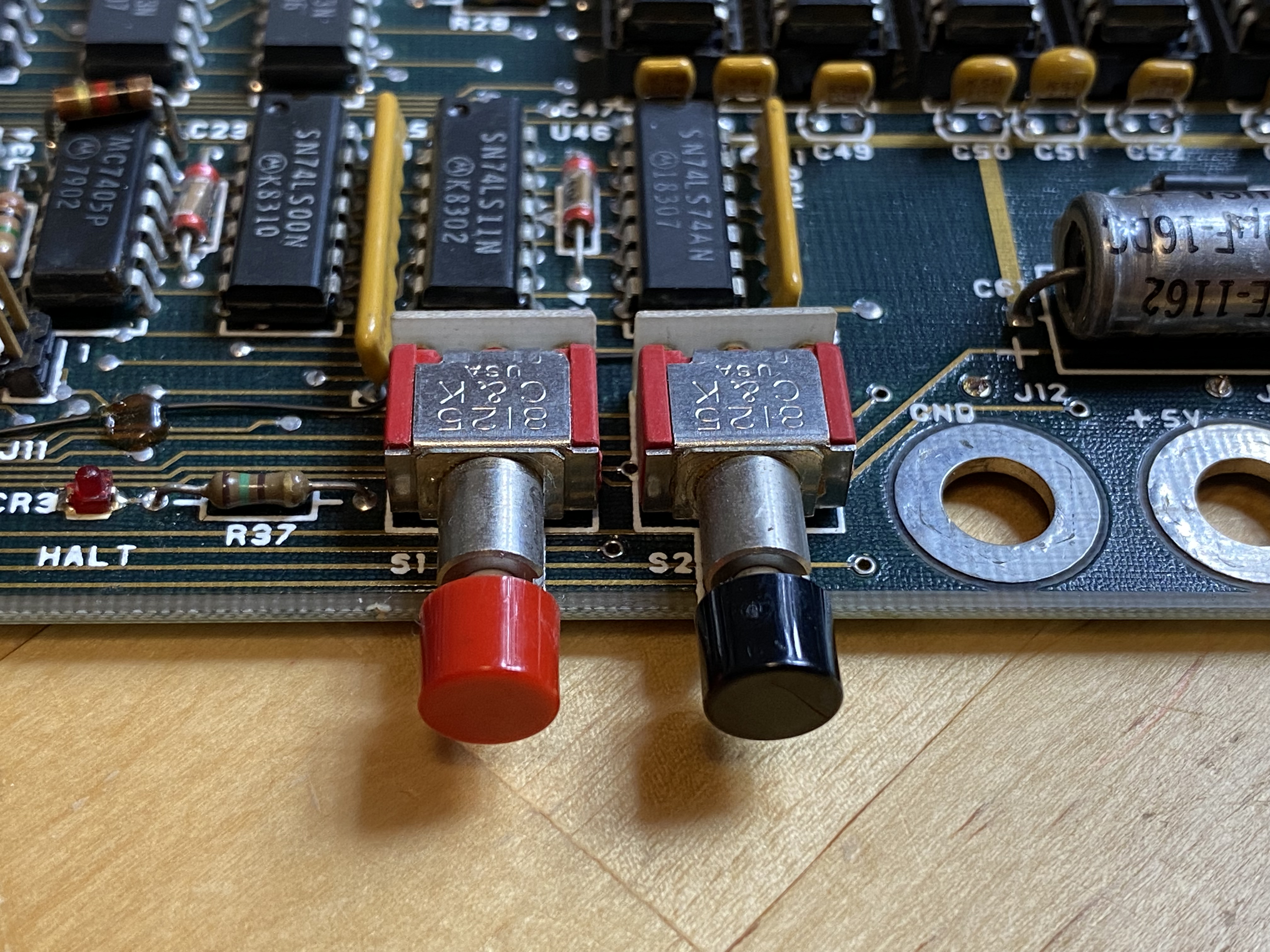
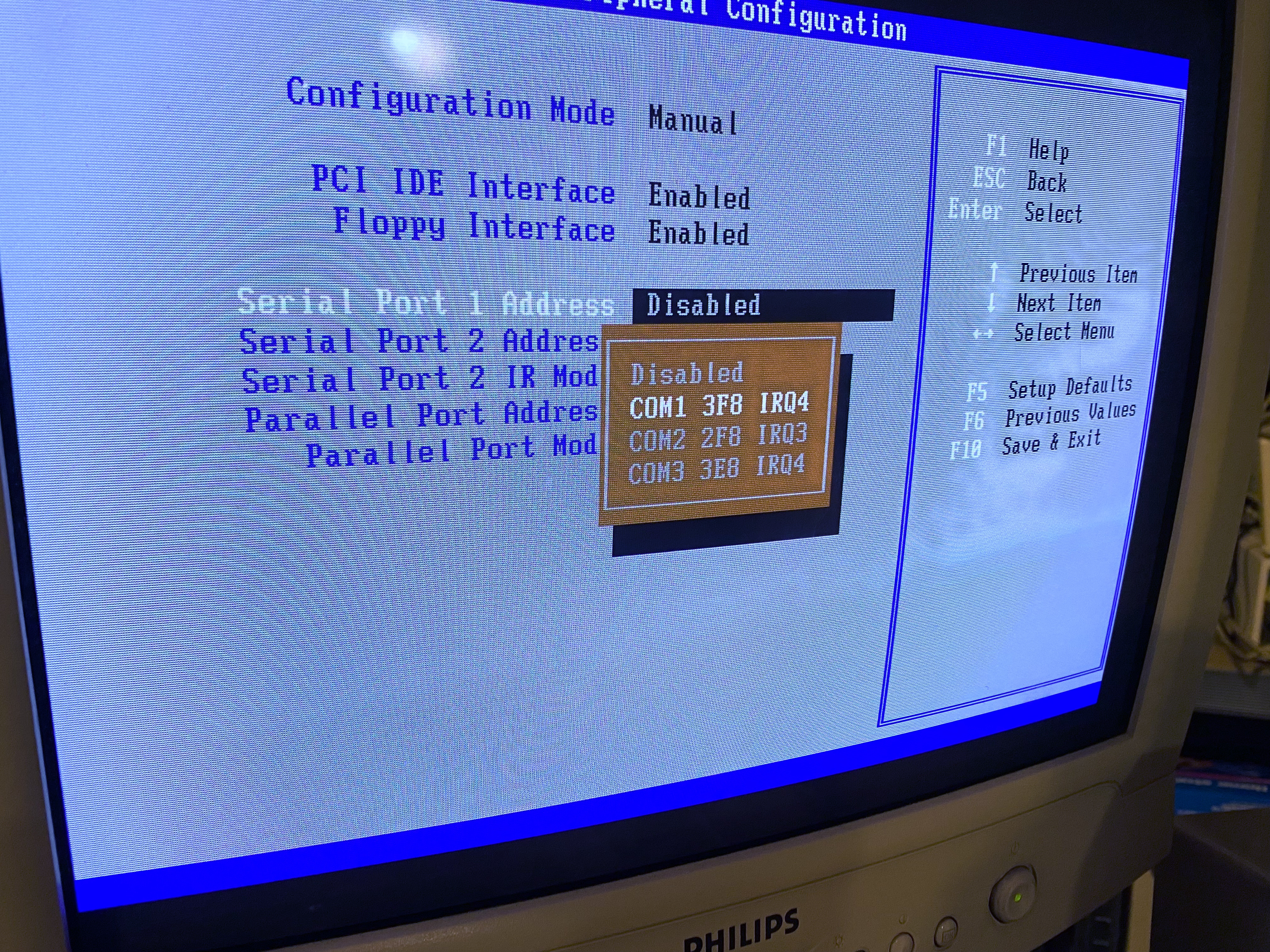
Next, connect a terminal via the serial interface on Port 1. I really wanted to try the board out still before I bought the proper edge connectors, so I soldered the wires to the pins, connected them in straight (not crossed) manner to a DB9 plug, connected the plug to an old MS-DOS machine, loaded Kermit terminal software on an that machine, and hoped for the best. And... it didn't work. The ECB seemed to power on (there is a program halt LED which comes on when the ECB starts up), but Kermit didn't seem to receive any signal from the board. Nothing was displayed on my PC's screen. I spent hours checking the connection parameters, including whether Kermit's console setting matches the expected 9600 baud, 7N1 setting of the ECB, and tried different serial wire connections (TX to RX vs RX to RX), to no avail. And finally it dawned on me that the serial port on my PC may not be enabled at all in the BIOS... which turned out to be the case. Having rectified that, the rest was smooth sailing: Kermit displayed TUTOR 1.3> prompt (probably for the first time in decades of this board's life), and I knew I was onto something.
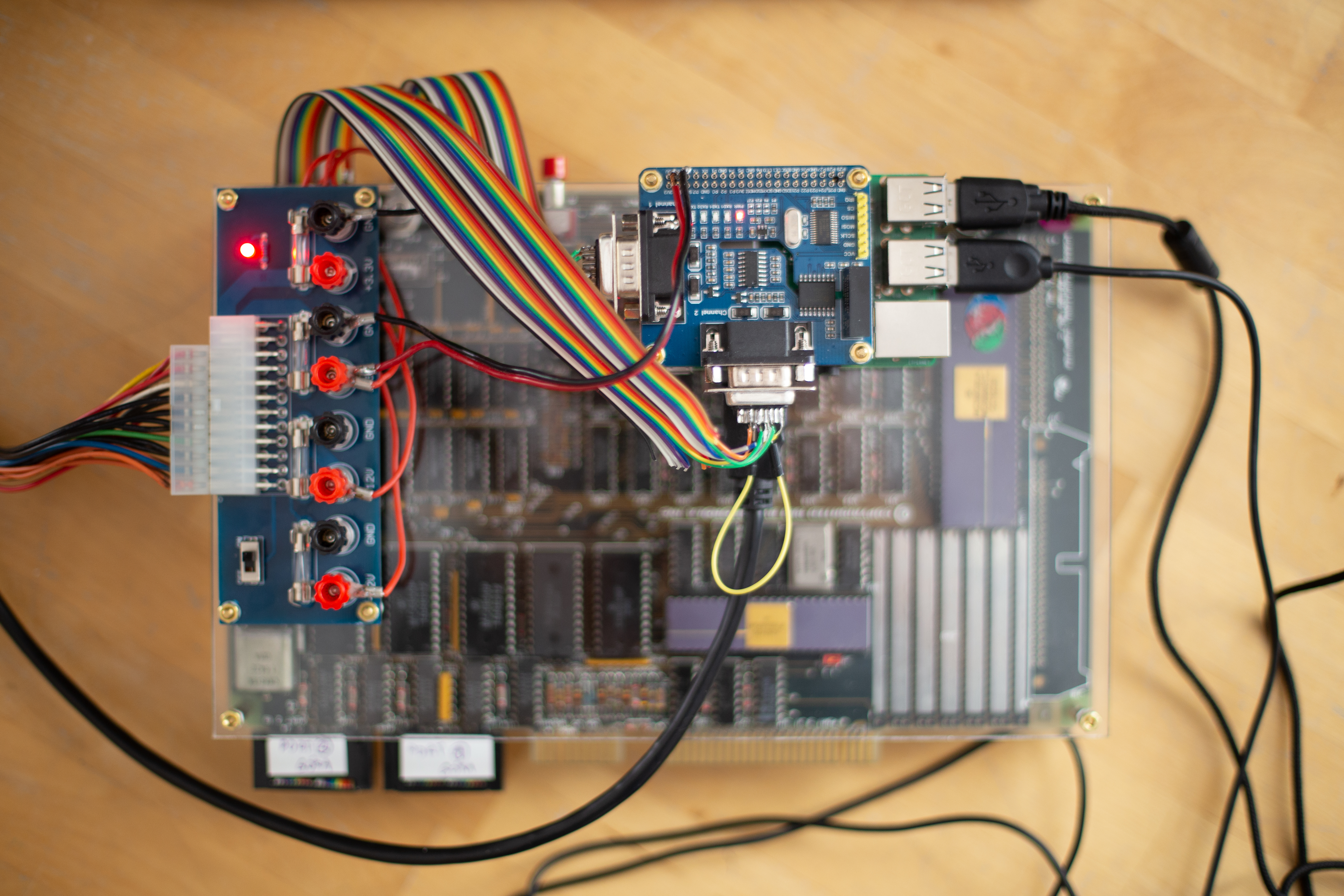
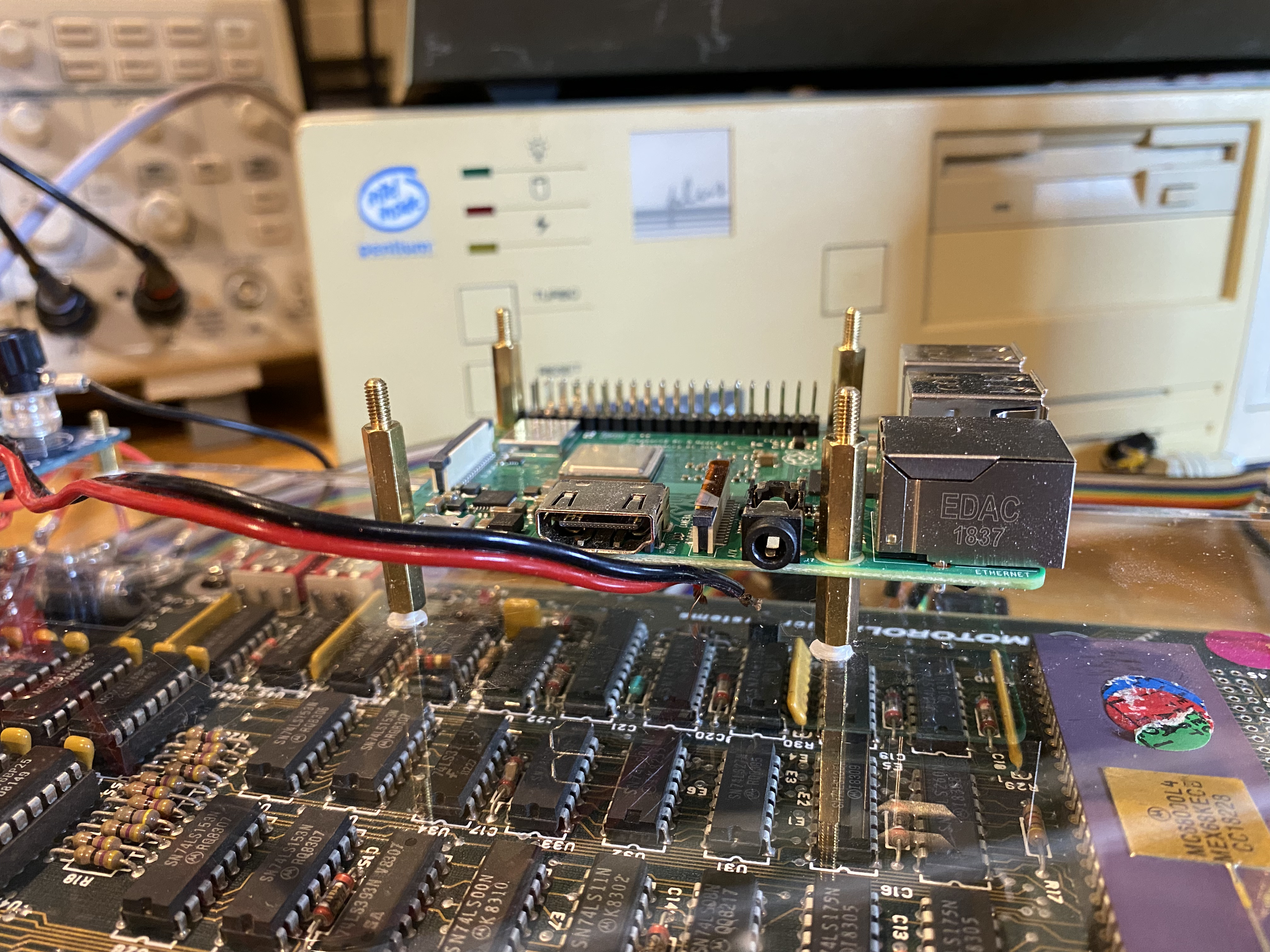
To ensure reliable power transfer from the ATX power supply to both the Motorola ECB and Raspberry Pi, I bought and installed an ATX power transfer board which has an ATX socket on one side, and convenient cable connectors for each voltage line and ground on the other. It is also equipped with a switch which eliminates the need to shorten power on pins on the ATX supply plug. Finally, the power transfer board I bought also has four mounting holes which made it perfect for my project. In addition to connecting the ECB itself, in parallel I connected the Raspberry Pi. It is good to make sure the power connection to Raspberry is reliable, especially if one doesn't use the usual USB power supply, but provides own power source via 5V and GND pins of the GPIO header as I did here. Even though the power requirements of both Raspberry Pi and the ECB, totalling at around 3000mA at 5V and 50mA at 12V were well below the limits of the ATX power supply, when I used thinner cables with inserted plugs, I got Low Voltage warnings on the Pi. The problem was solved when I replaced them with thicker 20AWG cables and, instead of plugging, soldered them onto the GPIO pins.
After I had seen the board display its prompt in MS-DOS Kermit, I thought achieving the same on the Raspberry Pi would have been trivial. In the end, a serial connection is just a serial connection, and a terminal emulator is just a terminal emulator. They should all work the same everywhere. I couldn't have been more wrong.
First, my Raspberry Pi 3 B+, or any Raspberry Pi for that matter, comes without RS232-compatible serial port. It does have an UART serial communication device, but it operates at lower voltage (3.3V) than RS232 which supports voltages of 5 and more volts. So connecting receive/transmit lines from the ECB to the Pi would likely result in frying the latter. An RS232-compatible serial port had to be added to the Raspberry. I started by plugging in an old USB-RS232 converter I had lying around; I did manage to see the TUTOR prompt on the screen, but the connection was exteremely unstable, with ECB crashing with SOFTWARE ABORT message and a stack dump every few characters typed. No changes of serial communication parameters helped, so I wrote that USB adapter off. That old and cheap adapter was most likely either faulty or not fully standard compatible, but more importantly I didn't really want a USB adapter in my project: I wanted direct serial connection.
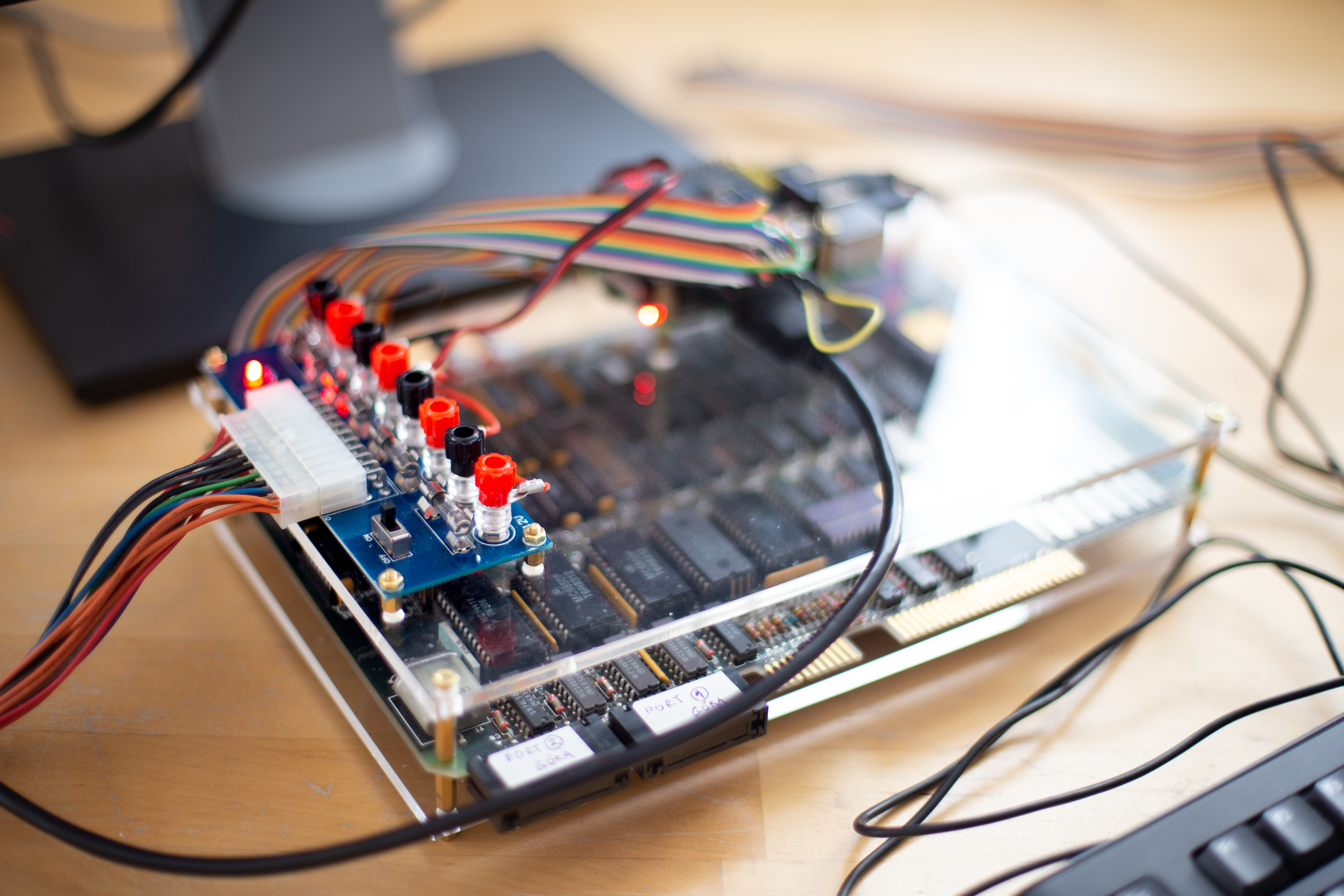
As the next step, I purchased two UART-RS232 conversion hats for the Raspberry, a simpler one with one DB9 port, and a more advanced one with two ports. It didn't take much time to settle on the latter: not only did it allow me to use the Raspberry Pi for two purposes (one serial connection as dumb terminal, another for host communication), but also it was equipped with LEDs to display the status of each of the serial ports transmit (TX) and receive (RX) status lines. Those LEDs turned out to be exteremely helpful in troubleshooting the serial connections between the ECB and Pi. In addition, I purchased 20-pin edge connectors for each serial port, and a matching rainbow-colored ribbon cable. The pin pitch, that is the distance between the centers of the pins on the Motorola ECB's edge connector, is 2.54mm so I had to pick a matching edge socket; the ones I had for my Commodore 64 projects wouldn't work as they had a different pitch. Instead of purchasing a new ribbon cable I could have also repurposed one of the IDE disk ribbons which have the same matching 2.54mm pitch.

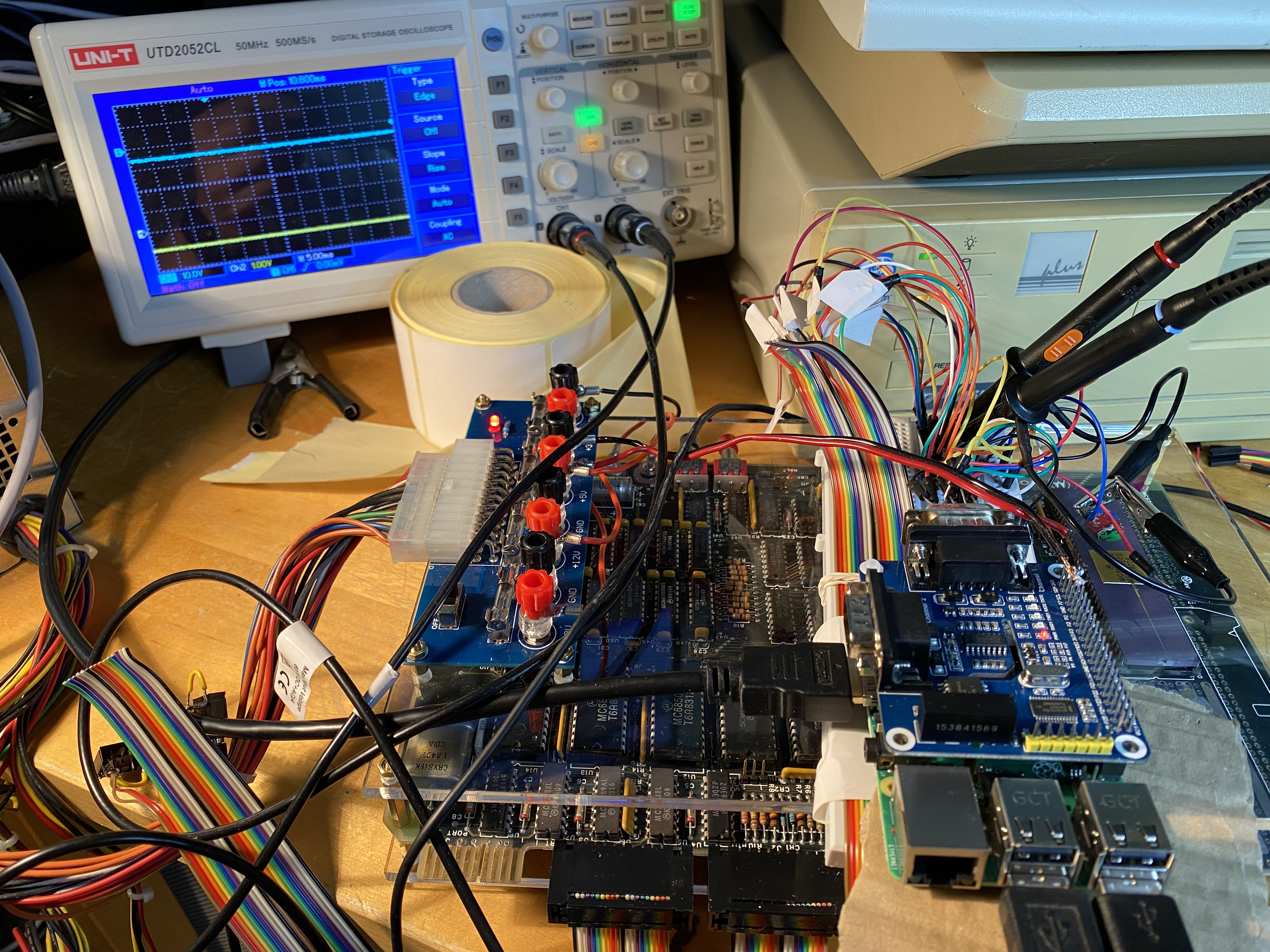
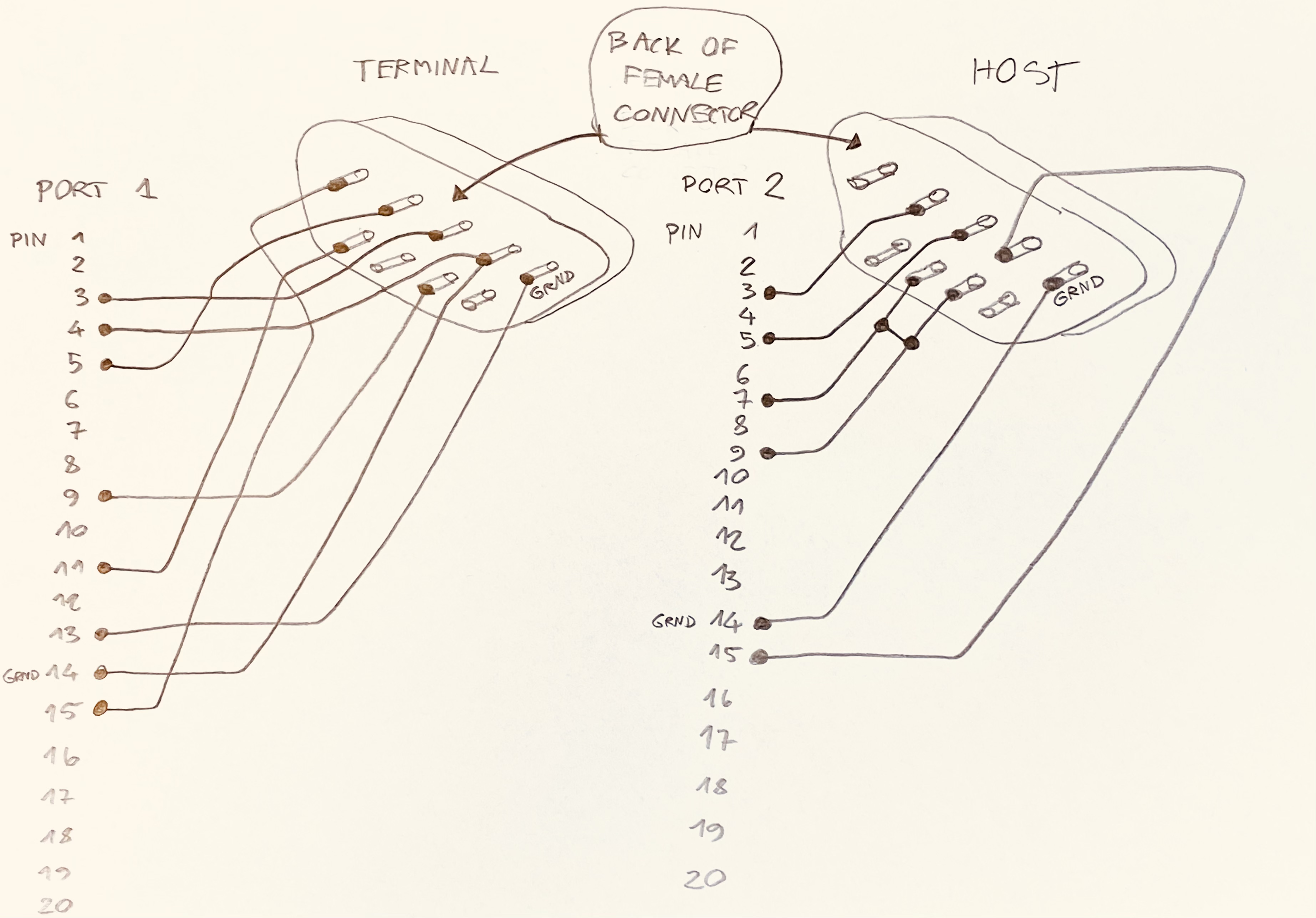
The biggest challenge was to figure out which pin of the Motorola ECB was supposed to be connected to which pin of the RS-232 port. That was the most time-consuming part of the entire project. The ECB manual provides instructions for how to connect individual ECB pins to specific RS232 pins, but the pinout is provided for the older-type DB25, so the first obstacle was to translate that to DB9 pinout. Moreover, each of the board's serial connectors behaves in a different way, with Port 1 (for dumb terminal) acting as a DCE equipment while Port 2 (for host) as a DTE (see references for a link to what these mean). But even though I got the connections right as per DCE/DTE pinouts, I still wasn't able to get any signal from the ECB to the Raspberry Pi. According to the flashing LEDs on my RS232 hat, transmission was happening from the Pi to the ECB when I pressed keys on the keyboard, but nothing was being sent back. The exact same connection to an old PC with Kermit installed worked perfectly, with bi-directional communication. I was stuck and decided to get my oscilloscope and investigate deeper.
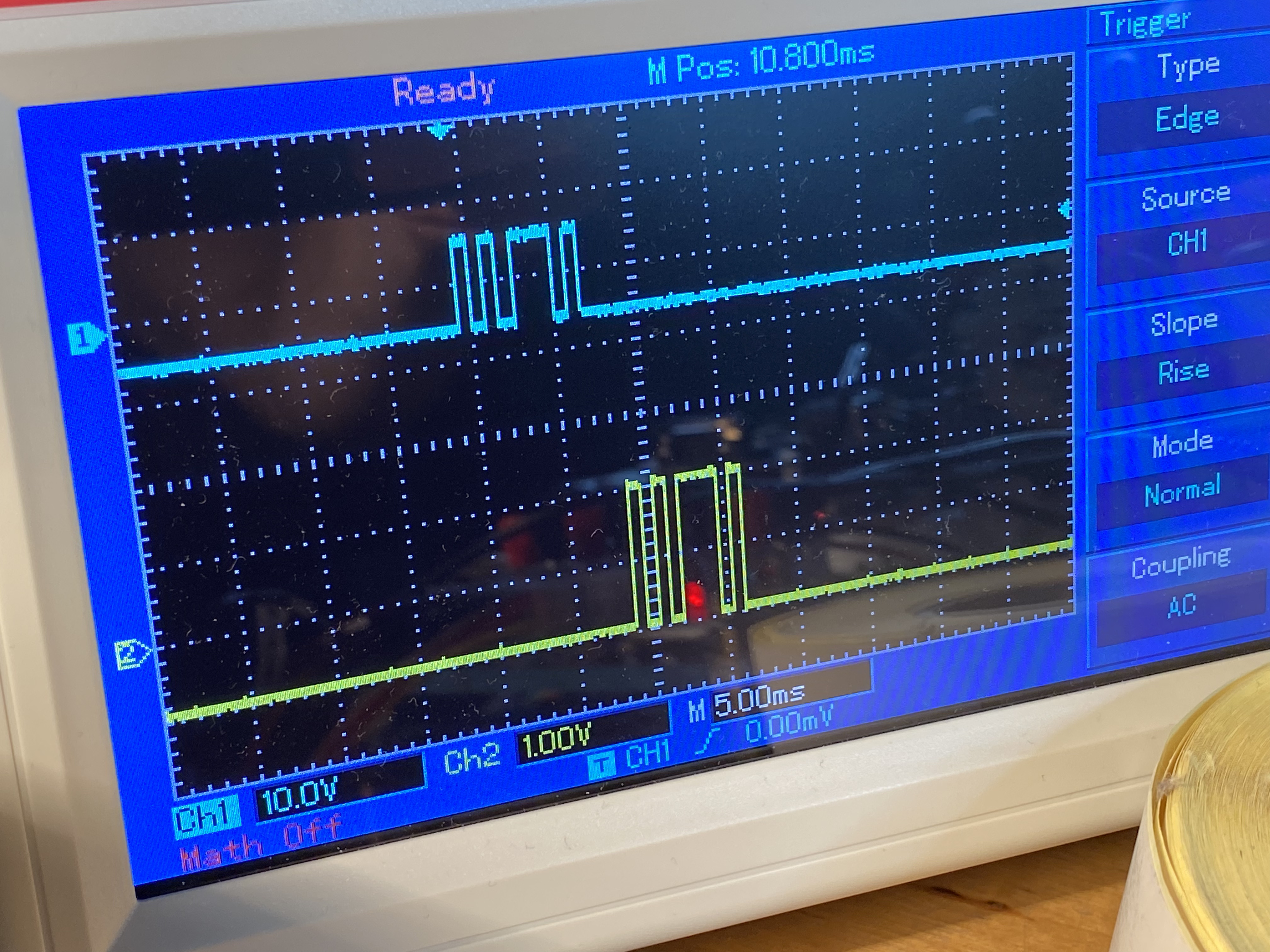
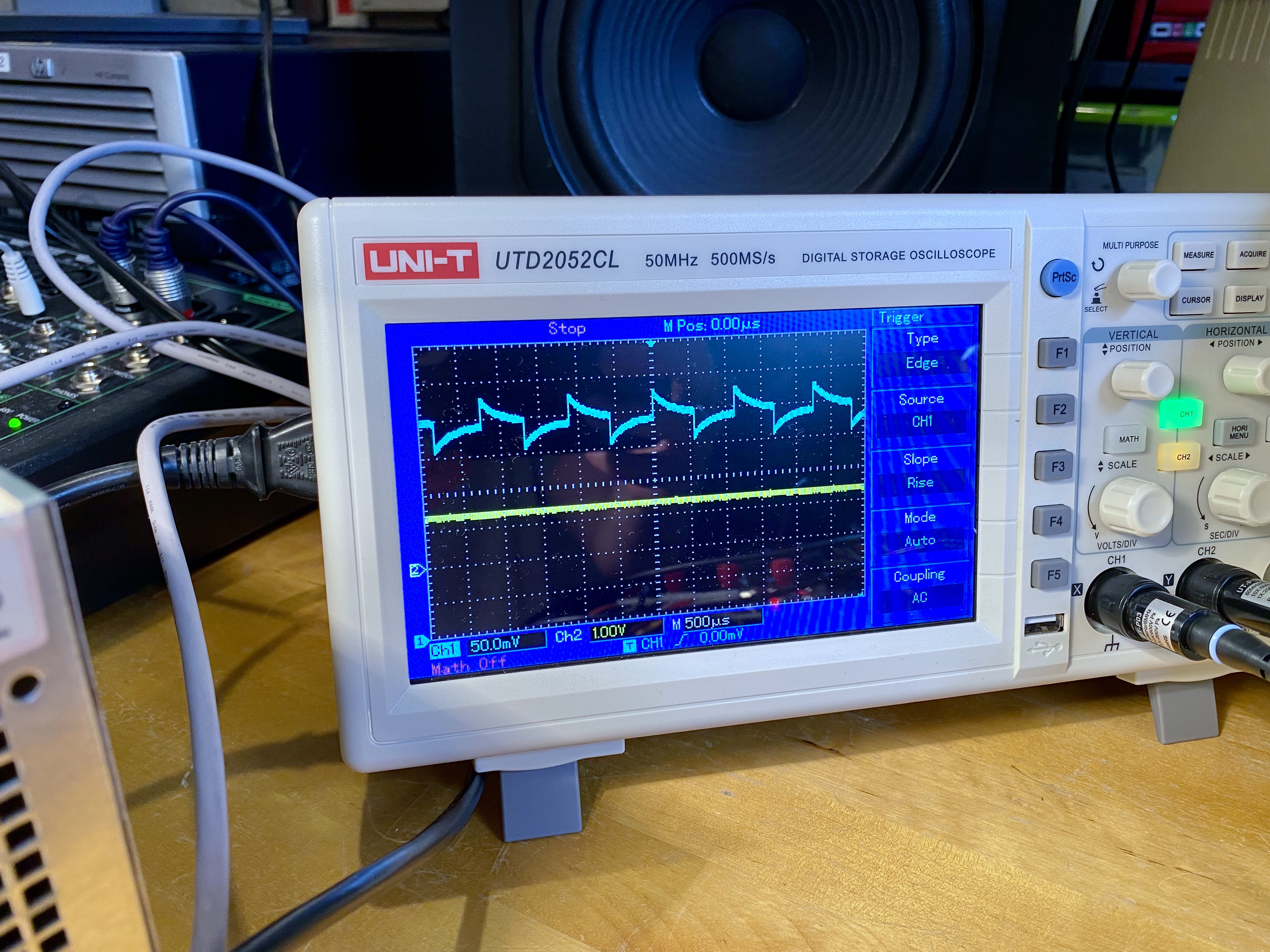
It is quite amazing how much one can learn about serial communication by looking at just one oscope screen. After connecting one probe to TX line and ground, and the other one to RX line and ground, and setting the trigger I was able to observe the full exchange caused by pressing one key on the keyboard. Figure 19 shows the capital letter E sent from the PC terminal to the Motorola ECB, and echoed by the ECB back to the PC terminal. ASCII letter E has hexadecimal value of $45, decimal of 69, and binary 01000101. The transmission (blue line on the oscilloscope screen) starts by putting the line to high which indicates the start bit (first blue hump on the left), then there are 8 bits of data which are transmitted in Low-Endian order, i.e. least significant bits of the value 01000101 first (so: 10100010); note that in RS232 ones are transmitted as lower voltage while zeroes as higher voltage. Finally the line is put to low to signify the stop bit (end of current transmission). We saw eight bits of data, no parity (error check) bit, and a single stop bit, so the configuration is 8N1. We also see that one bit takes a little less 1ms to transmit (see horizontal axis of the oscilloscope), and this checks out with the 1200 baud rate at which I was testing: 1/1200 ≈ 0.0008333333333 ≈ 1ms. Finally, we can examine the voltage differences between high and low which are ~12V when transmitting to ECB and ~2V when receiving from the ECB.

But all that watching of the communication between the ECB and PC still didn't help me understand why data is transmitted from Pi to ECB, but never received from ECB to Pi. Finally it dawned on me that the issue might not be in TX/RX lines at all, but on some other supporting serial lines, and I went back to re-reading the manual. And there it was: in the appendix, conveniently hidden from anyone trying to set the board up for the first time, there was a brief note about how this specific implementation of RS232 works, and in particular how switching the RTS line to low is required to start communication, and how putting it to high instead enables the Transparent Mode of the ECB, a special mode where anything transmitted to the terminal connection (Port 1) is simply passed through to the host connection (Port 2). This was definitely a eureka and a cry of relief after hours of desperate try and error. I could only blame myself for not RTFM; in my defense, the various aspects of ECB's serial communication are scattered around many sections of the manual. Having resolved the issue I was now able to document the working connections for posteriority.
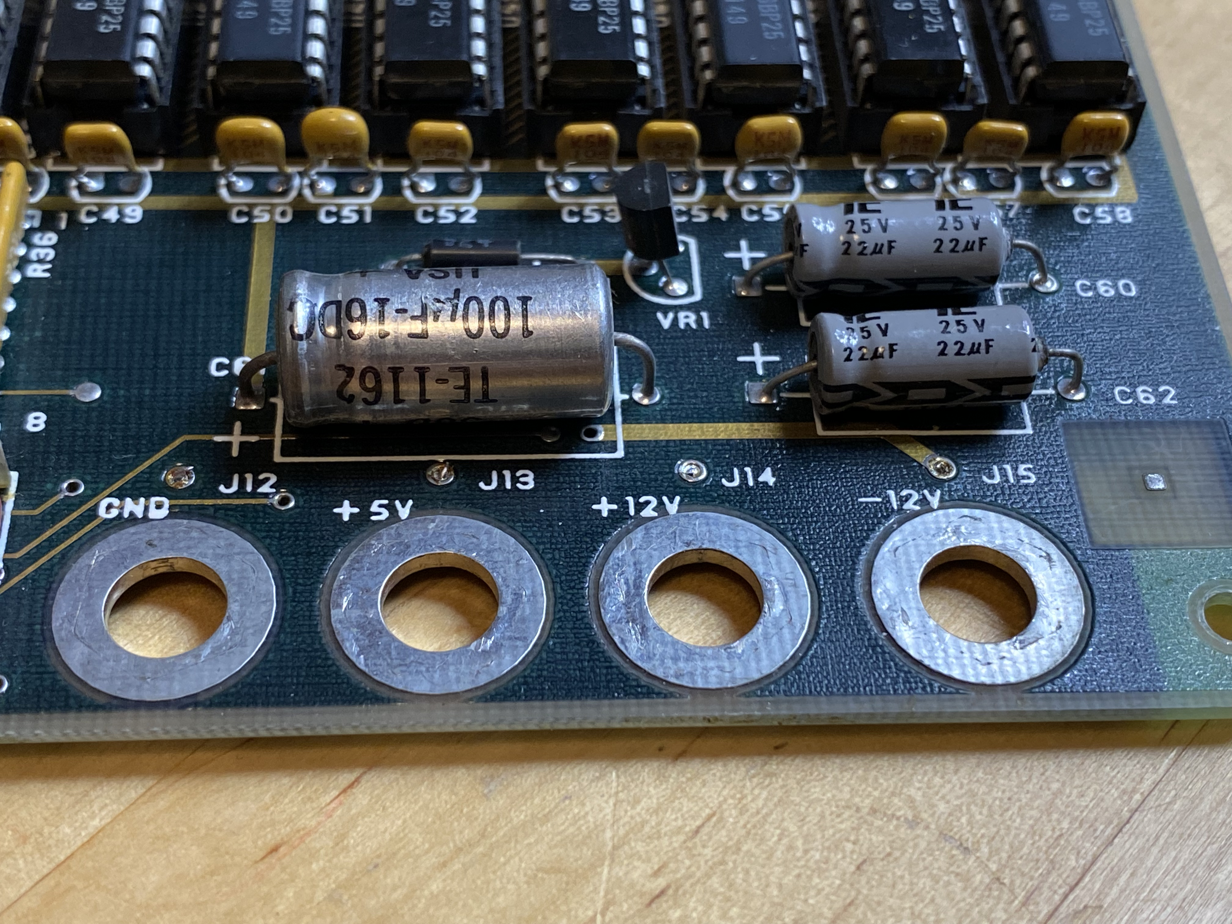
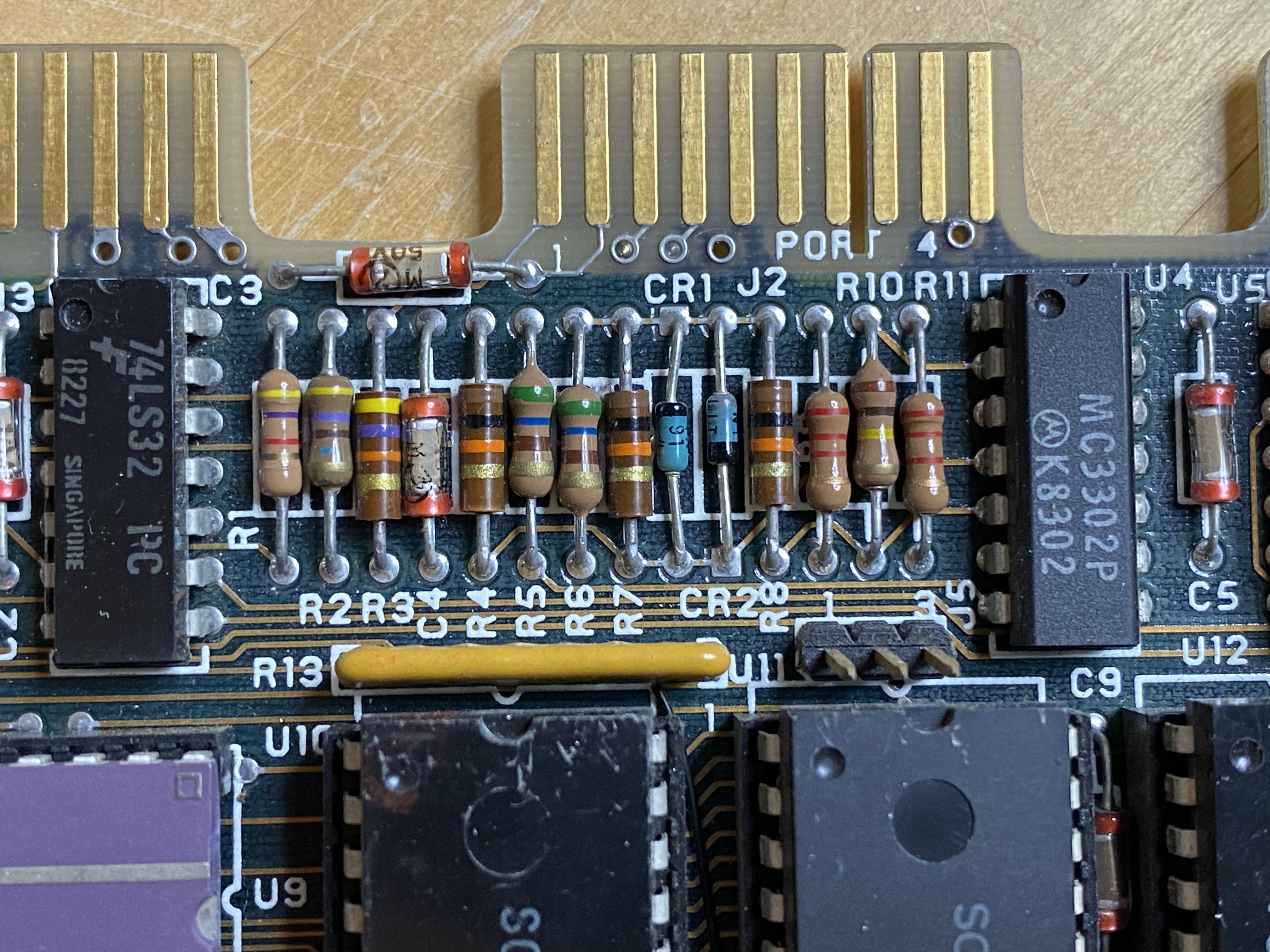
The ECB is also equipped with another serial port (Port 4) which outputs audio signal and allows dumping memory content to a magnetic tape. I briefly tried it out and even managed to save data and restore it (to a wav file though, not actual tape), but found this way of saving programs extremely unreliable. One reason for that is that the shape of the audio wave on the connector was not really square which prompts me to believe the ECB might be in need of recapping. The capacitors by the audio connection are ceramic which are unlikely to fail, but the ones by power supply lines are electrolytic and I may want to replace them shortly. In any case, I feel like I want to revisit the tape connection subject sometime later.
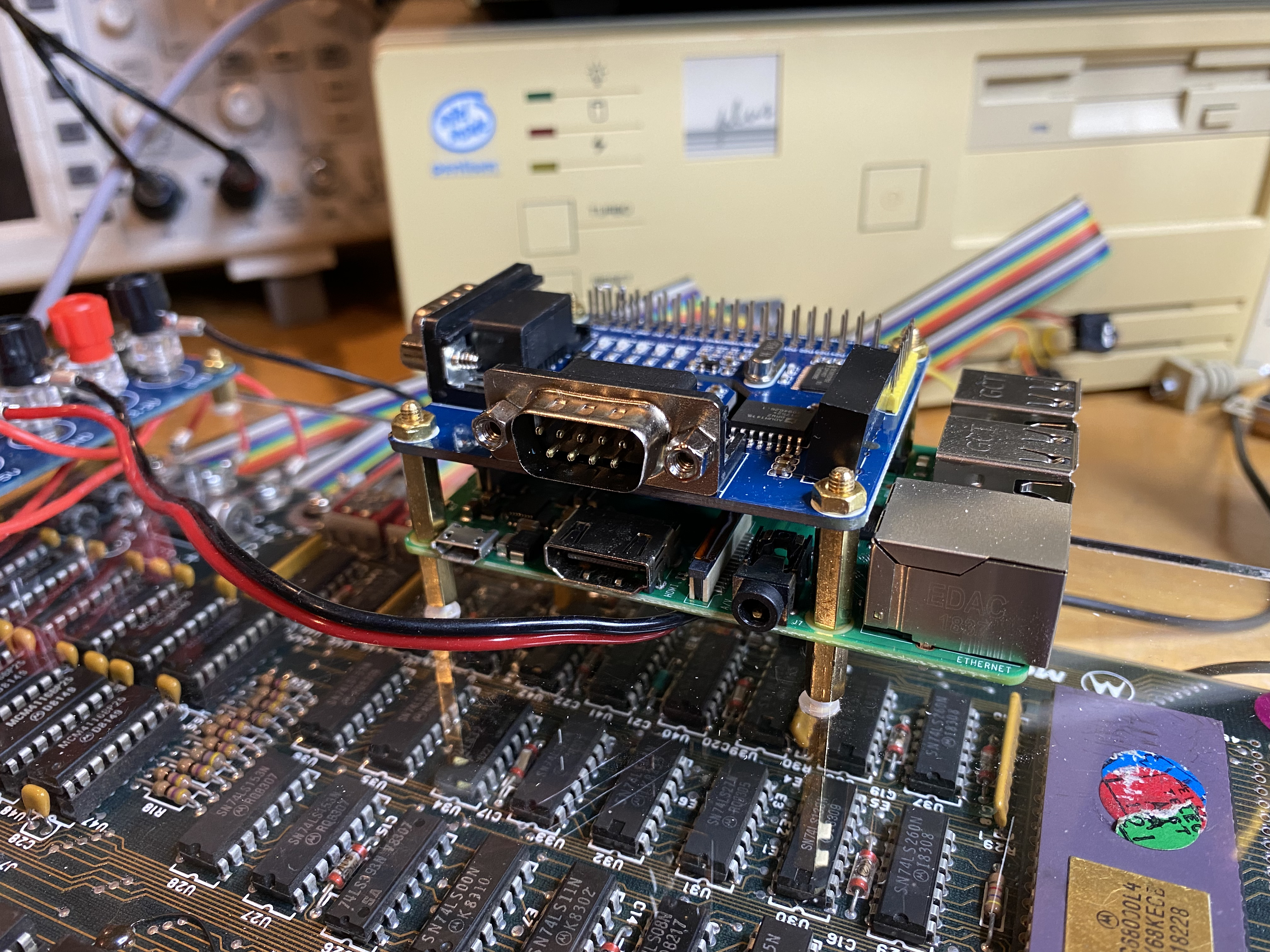
I didn't like how the Motorola ECB was resting directly on the table, so I ordered acrylic sheets, laser-cut to the same dimensions as the board. For assembly I used metal spacers, screws and nuts. I used the same M3 screws for attaching the Raspberry Pi to the top sheet, and then the RS232 hat to the top of the Raspberry Pi, and that required drilling through Raspberry's mounting holes which are slightly narrower. Since most of my troubleshooting revolved around the RS232 hat, the design keeps the power attachment and the Raspberry on top. When I'm ready to start fiddling with custom circuitry on the ECB board itself, I may want to swap them, moving the Pi and the power section to the lower floor while putting the ECB on the top.
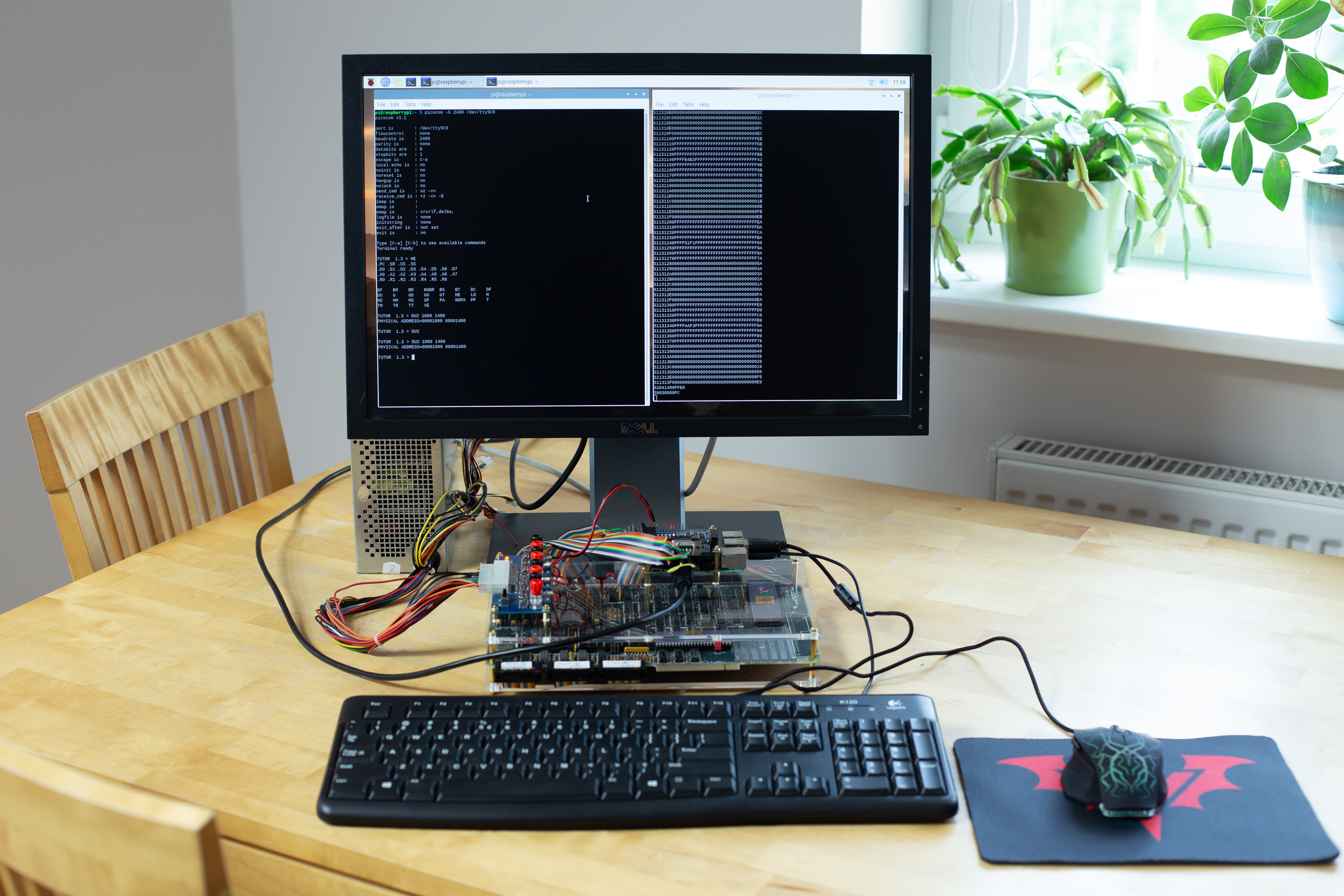
Here are the steps to enable two RS232 ports on the Raspberry Pi for communication, and to start communicating over the serial console. I spent a lot of time troubleshooting this so that you don't have to. The steps are for Raspberry Pi 3 B+, and for WaveShare 2-Channel RS232 HAT. If you use a different RPi or a different serial hat, the steps may be different.
sudo apt-get update and sudo apt-get upgrade./boot/config.txt file make sure that the line enable_uart=1 is enabled, and also add a new line dtoverlay=sc16is752-spi1,int_pin=24. This setting is specific to the RS232 hat I'm using, and it enables 2 additional serial logical devices /dev/ttySC0 and /dev/ttySC1 corresponding to two DB9 RS232 connectors on the hat. When using this hat and this setting, there is no need to disable Bluetooth (which you may need to do with other hats or serial interfaces, in particular those using /dev/ttyAMA0), in other words there is no need to uncomment #dtoverlay=disable-bt.sudo apt-get install picocompicocom -b 9600 /dev/ttySC0. Use the same baud rate as the one configured with jumpers on the ECB board (by default 9600.7, parity to none, stopbits to 1 (default Motorola ECB settings).TUTOR 1.3> prompt being displayed in the picocom window. Congratulations — you are now talking to Motorola 68000 ECB!
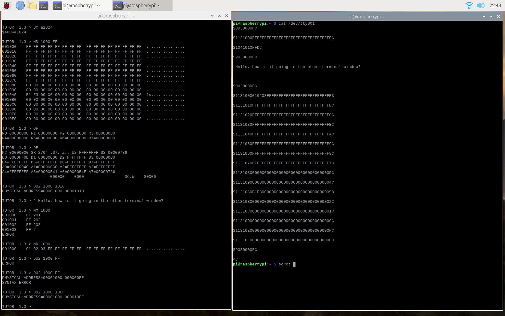
The following Python script, when launched in a terminal window separate from the one where TUTOR is run, listens to the selected serial port (in our case /dev/ttySC1 until it detects a data dump coming from the Motorola ECB. That event is triggered by issuing a DU2 .... command in TUTOR. When that happens, it recognizes the beginning of memory dump, and the end of it, and writes iall received data to an S-Record format file, using current date and time as the name, and ".s" as suffix. It works in a loop, so after saving a file it just waits for another transmission. This way, while working in TUTOR, one can frequently make memory dumps which serve as either final files or intermediate backups. The script is, however, very basic, and can be easily improved to do at least some error checking, to recognize messages sent from TUTOR but not constituting a part of file (using the asterix * command), and to use DU2 command's optional text parameter for example as the file name.
The next script does the opposite: it takes an S-Record file as an argument and — after LO2 command is issued in TUTOR, it uploads it to the Motorola ECB. Similarly to the receiving script, this one can also be enhanced. I'm planning to add the support for LO2 command's text option support which will help trigger file sending from within the ECB.
We are not aming here to cover the ECB's innovative built-in program TUTOR, as it is interesting enough to deserve its own article. Besides, included in the reference is a link to the board's manual which does a great job explaining the software's functionality. I'm going to write a separate article and make a separate video on the subject.